During the Covid lockdown period there is always plenty to keep one occupied – particularly in the equipment maintenance department.
In this article, we will go through the process of refurbishing this circa 1990 antenna which, back in the day, was sourced from Andrews Communications when they had their store at Maroubra in Sydney’s Eastern Suburbs. So, let’s commence with a trip back down memory lane looking at a full page advertisement in the September/October 1989 edition of CB Action Magazine for Andrews Communications.

Page 50: CB Action September/October 1989 
Page 51: CB Action September/October 1989 
The above close up view of Page 51 depicts this antenna made by Waldor Enterprises.


The above close up view of Page 51 depicts this antenna made by Waldor Enterprises. The company is defunct and doesn’t even come up on Google search engine. At the end of this article are the assembly instructions that were provided with this antenna.
Also, check out the prices of other offerings from Andrews Communications back then. A Cobra 148GTL for example, would have cost you $400.
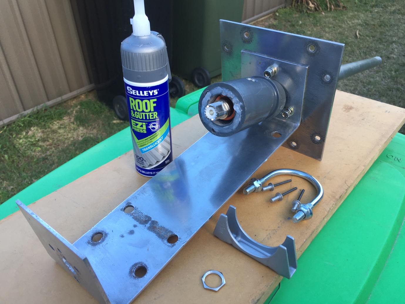
So, without any further ado, let’s have a look at the various components of this antenna and give it a birthday.

In this photo, the vertical radiator and ground plane base plate have already had a clean up. 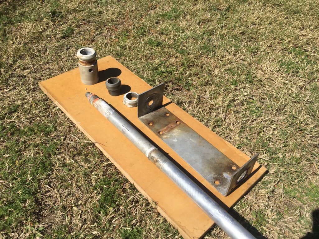
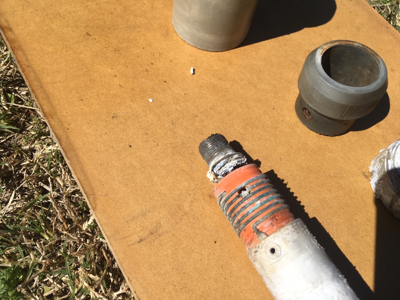
The base assembly needs to be disassembled in a particular order. 
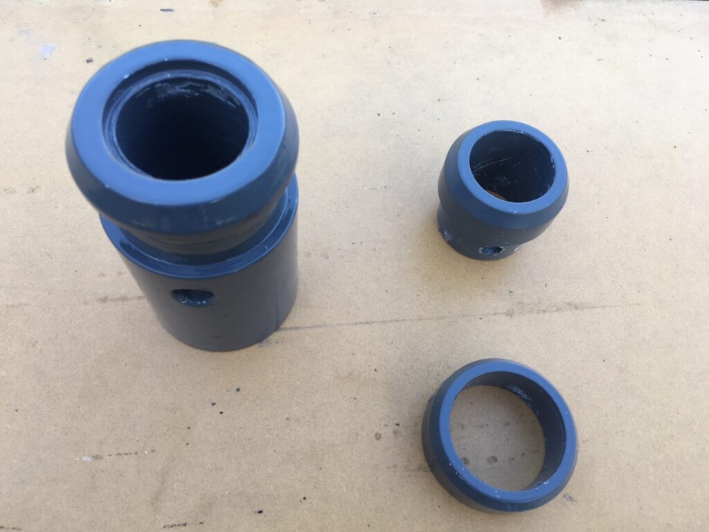
A close up view of the bottom auto-transformer assembly. It has seen better days.


In the first photo, the vertical radiator and ground plane base plate have already had a clean up using a bit of 600 grade wet and dry paper “wet” in a bucket of water. This assembly makes use of 2” zinc plated muffler clamps. The top plastic bushing, bottom plastic housing and SO-239 connector have weathered over the last number of years as the antenna has been stored outside along a fence.
You can see in the next photo that assembly needs to be disassembled in a particular order. The auto-transformer assembly is visible at the bottom of the aluminium tube. This assembly and tube bottom are held in place – both mechanically and electrically using a single rivet that also goes through the hole on the side of the bottom plastic housing.

This auto-transformer has been cleaned up the best it can be .
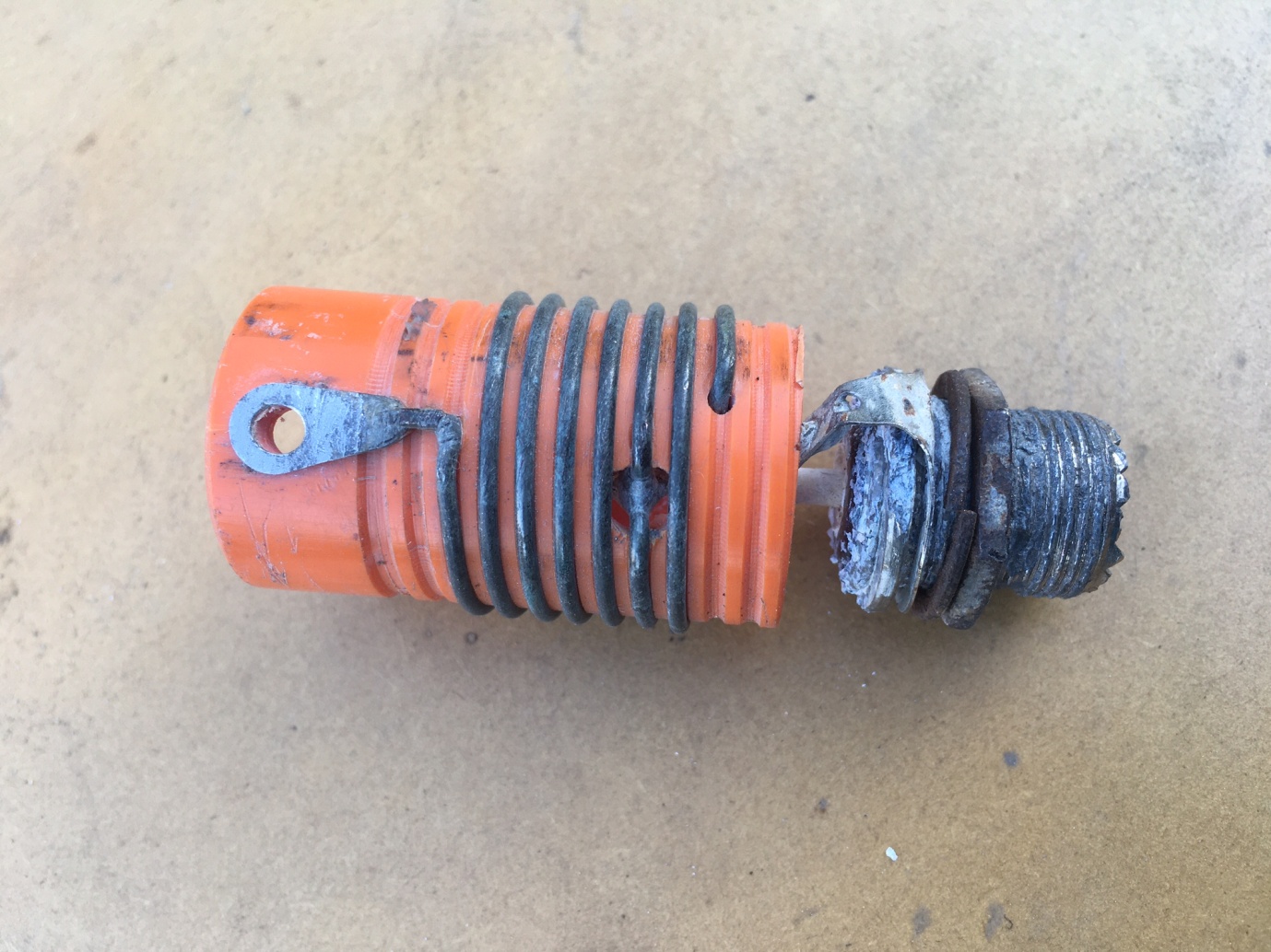
This auto-transformer has been cleaned up the best it can be using a combination of a small wire brush and some bi-carbonate soda. That SO-239 is not much good and we will need to source a replacement. For both half wave and five eighth wave antennas the impedance at the bottom of the tube is not 50 Ohms, hence the requirement for some type of matching network. A five eighth wave antenna will be somewhere around 625 Ohms so we need some type of impedance transformer to bring the feed point to 50 Ohms. The lug is the high impedance point connection onto the aluminium tube. Where the hole is in the former, this tapping point going to the centre pin on the SO-239 has been worked out to be the 50 Ohm point. The end of the coil is connected to ground on the SO-239 connector. The former appears to be a piece of conduit with a helix cut into it using a lathe to keep the coil spacing even.
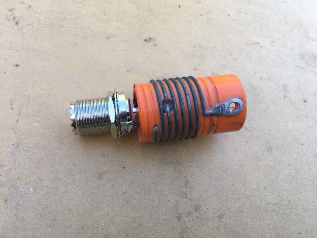
That now looks a whole lot better- a brand new SO-239 connector.

There are two types of SO-239 chassis mount connectors. One type is fed through the hole in the chassis with the star washer and nut done up on the same side as the centre pin soldered connection. The other type has the star washer and nut done up on the OUTSIDE of the chassis. We need the latter due to how the antenna is required to be reassembled. They are also difficult to come by, this one coming from an amateur shop in South Carolina in the USA. What started out as a US$5.50 connector became a $66 AUD connector delivered to Australia.
To minimise any further weathering, the plastic components were coated with a plastic primer paint and a coat of grey Rustguard applied over the top. 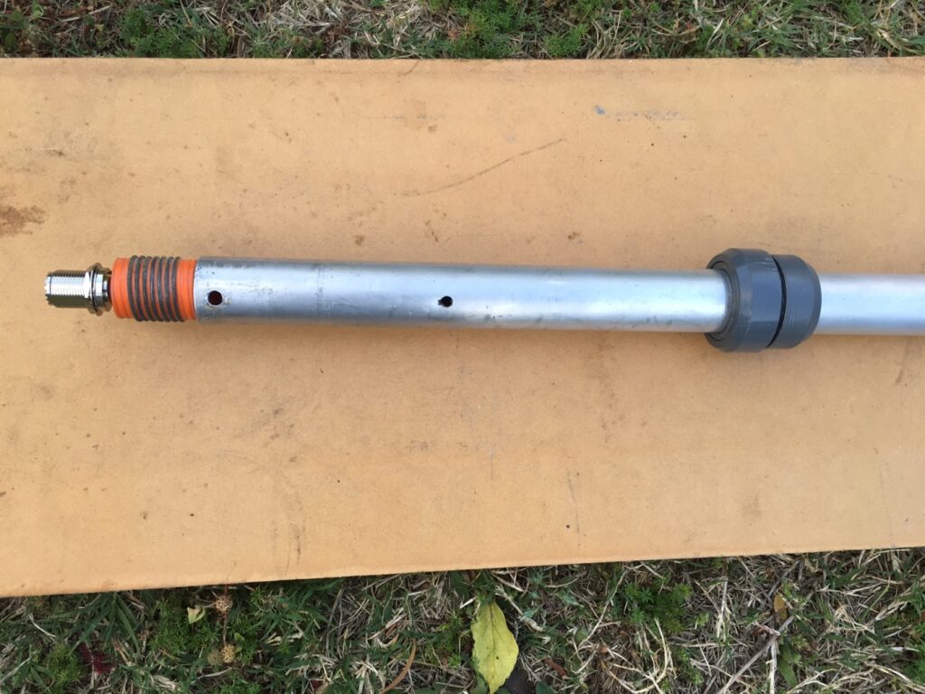
The auto-transformer assembly has been inserted back into the bottom tube and the rivet holes lined up. 
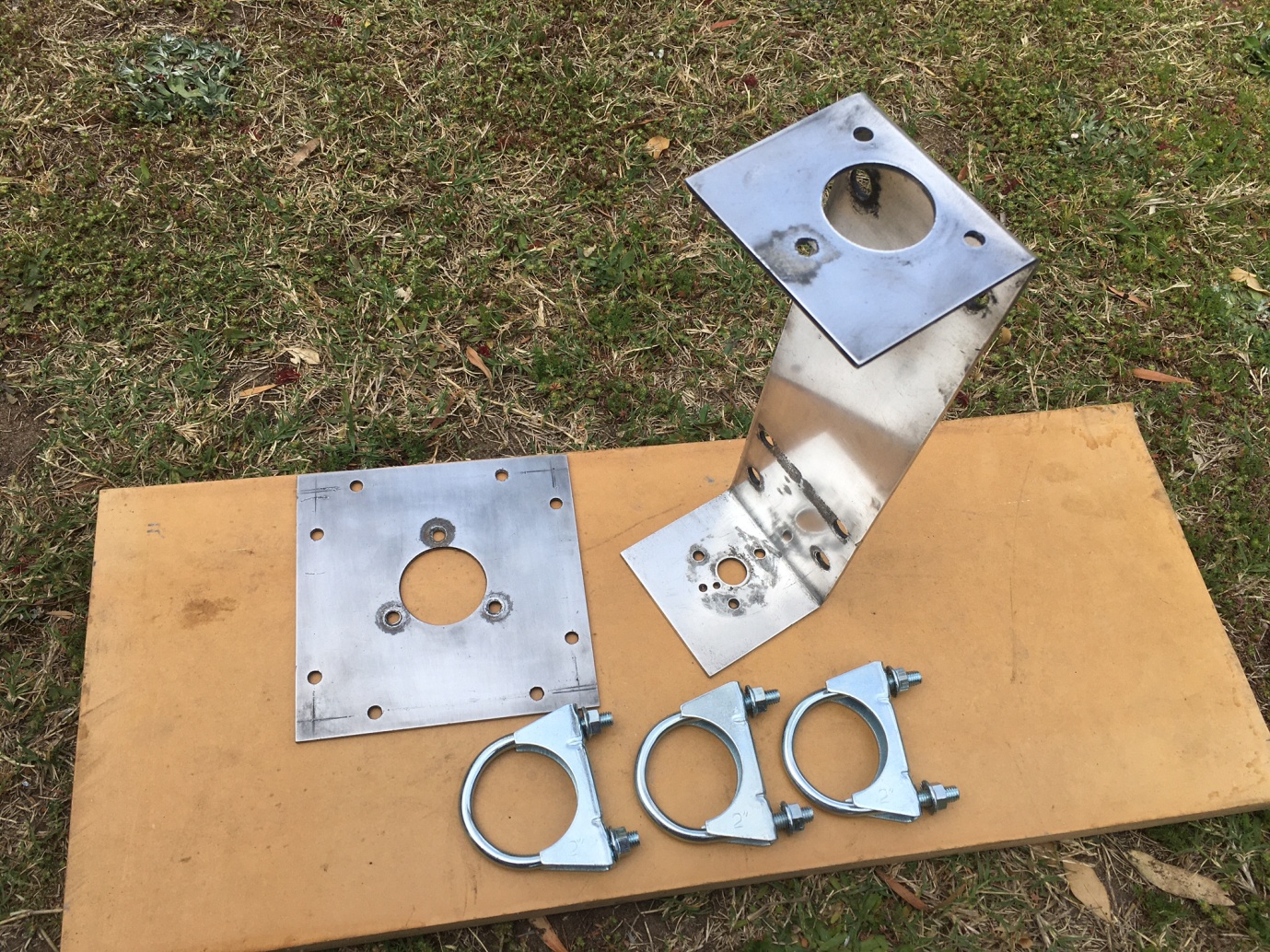
The ground plane plate and bracket have been given some metal polish, this is as good as it gets.


The plastic components could be remade relatively easily however a piece of plastic bar and access to a lathe is required. If this has to be paid for – labour and material wise, these will be the expensive parts.
You can see in the second photo above that the auto-transformer assembly was inserted back into the bottom tube and the rivet holes lined up. Just above this hole inside the tube is a plug of sealant so no chance of getting water down into the auto-transformer assembly. The hole to the right is a drain hole for the vertical radiator. It is clear now but it did have sealant in it prior.
There is some localised pitting in the bracket where the steel clamps and fasteners have been previously and are about to be again. The muffler clamps are new assemblies but as I am about to find out, the clamp holding the bottom plastic housing in place will need about 3mm filing out of the clamp saddle.

We are at the point where we are ready to assemble as we go. 
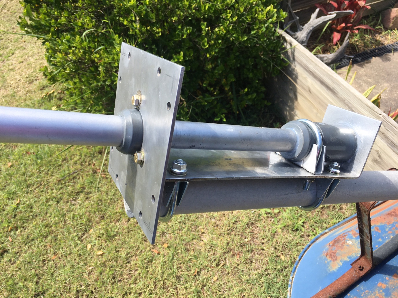
The next step is to slide the assembly down towards the bottom of the bracket. 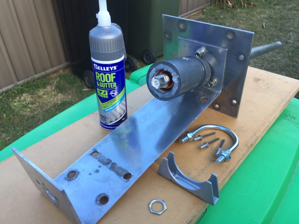
A small bead of sealant is put into the machined groove in the plastic base.


The top plastic bushing is held in place by a 8Gx12mm self tapping screw. Some sealant will be applied over it when complete. The bottom plastic housing is held to the base plate using three aluminium 3/6” blind rivets. Machined into the bottom of this plastic housing is a groove which will have a small bead of sealant applied and then allowed to go tacky before riveting in place to allow it to function as an “O-Ring”. The steel 3/6”x15mm rivet goes through the hole in the side of the plastic base after it has been positioned over the auto-transformer assembly (ie, there are three holes to line up). The steel rivet should maintain the electrical bond between the inside of the aluminium tube and the lug at the top of the auto-transformer assembly.
Once the bottom plastic housing is riveted in place, the next step is to slide the assembly down towards the bottom of the bracket, putting the support muffler saddle clamp in place before the SO-239 goes through the hole in the bracket. Once the bottom rivets are in place, the supporting clamp saddle is not able to be removed even if its U-Bolt is.
Next we are at the point where it is time to get some sealant out. A small bead of sealant is put into the machined groove in the plastic base and then allowed to sit for five minutes or so. This bead will essentially act as an “O-Ring”. The saddle clamp needs to be positioned before the SO-239 is put through the hole in the bottom of the mounting bracket. The remaining things to do are:
- Place the star washer and nut over the SO-239 and do it up tight after aligning the rivet holes. Be satisfied that the SO-239 is sitting square to the bracket.
- Put the U-Bolt over the plastic housing and do up the nuts. I ended up swapping these flanged nuts for stainless steel nyloc variants.
- Place the 3/16” aluminium blind rivets in their holes and pop them. Check that the drain hole in the bottom of the aluminium bracket isn’t covered with sealant from our O-Ring.
- Slide the inside bushing at the top of the aluminium bracket into place and use a bit of sealant to keep it in place.
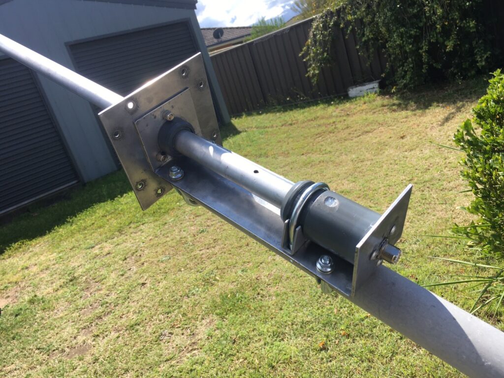
The completed bottom assembly mounted to a piece of 50mm Duralium tube. 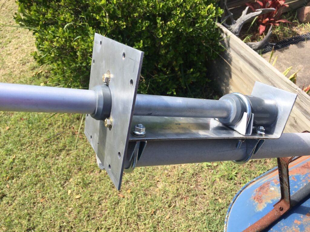
Another view of the bottom base assembly. I think we can agree that for a thirty year old antenna it has scrubbed up nicely.

It is now time to assemble the rest of the antenna and test it for VSWR.

A view of the Waldor Enterprises 5/8 Wave Avenger Mk 4 against a cloudy sky. 
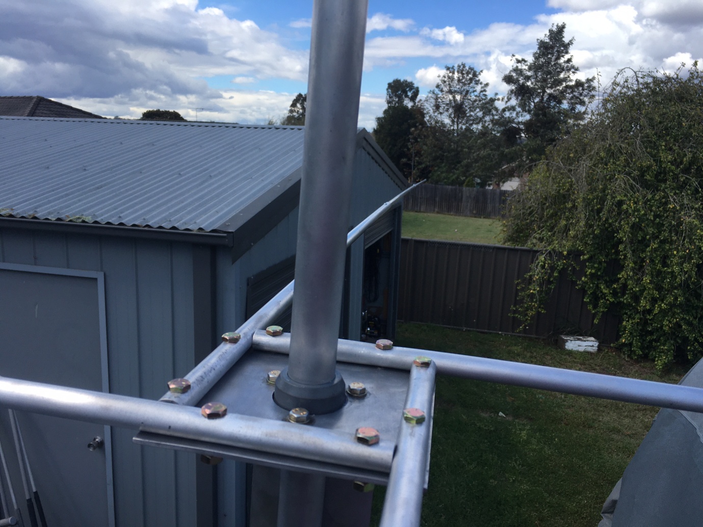
A close up view of how the radials attach to the base plate. 
The Rig Expert shows that the VSWR of this antenna is in the ball park – between 1.5 and 2.0:1.


It is interesting to note that when I had a second read of the installation instructions, the OEM specified placing the fasteners for the ground plane radials and plate such that the nuts are facing the sky, citing additional capacitance possibly affecting the VSWR if otherwise. The OEM also cites the same in relation to the surplus U-Bolt studs projecting into the bottom tube assembly. In other words, have just enough thread, no more. If you have a look at the previous photos my ground plane plate and radial fasteners were the incorrect way round which have since been reversed following the test. For now, we will say that this is good enough. In a real, practical installation this antenna would sit atop a 6m mast and the VSWR can then be checked when it is in its final mounting position which takes into account the surrounding environment.
Andrew Pain
2 October 2021